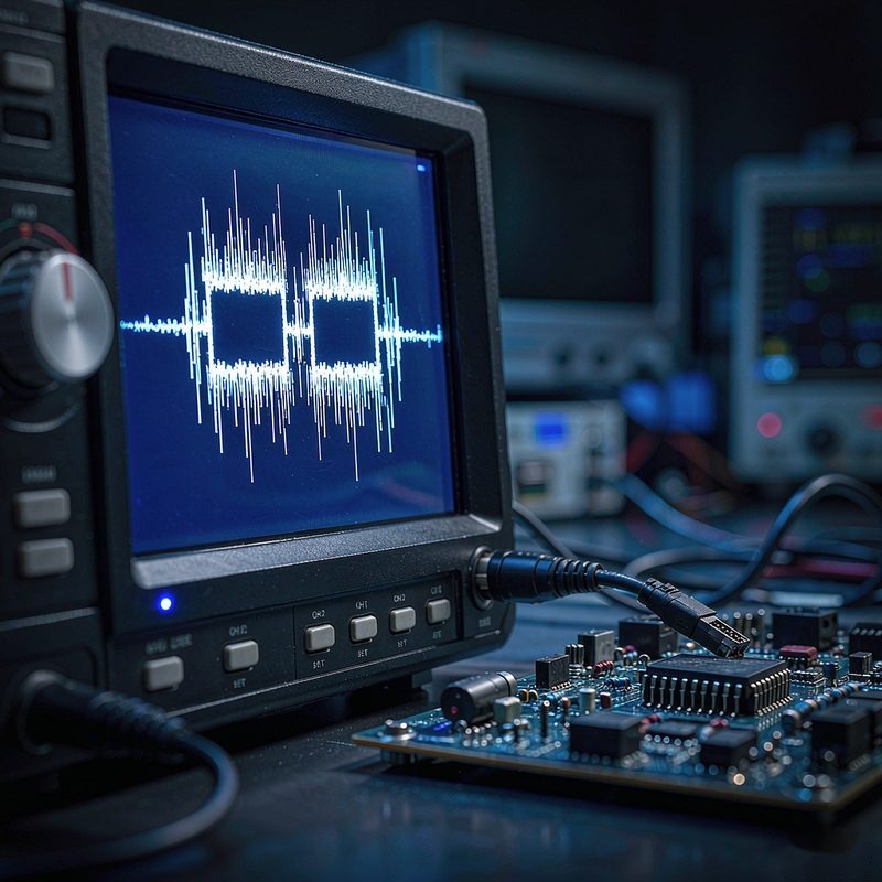
An EMC report comes back with a failure at 236 MHz, 3.4 dB over the Class B limit. The instinct is to open a design review: shielding, ferrites, stackup, clock edges. Before any of that, one question decides whether the redesign is needed at all - was the thing measured in the chamber the same thing you ship? In more cases than suppliers expect, it was not. The antenna saw a 1.8 m USB cable pulled from the lab's spare box, an auxiliary laptop charger sharing the same LISN, or a broadcast carrier that was already sitting near the limit before the product was switched on.
That is not an argument that failures are usually the lab's fault. It is a point about what a test report is: a record of one measurement of one configuration. Whether the failure is also a fact about your design has to be established separately, and the data needed to do it is normally already in the report package.
The short answer
It is a product problem if the failure survives the production configuration - the same cable length, the same adapter, the same firmware, the same accessories that leave the factory. It is a setup problem if it disappears once the configuration in the chamber matches the product, or if it traces back to something the test itself introduced: an ambient signal, a ground connection, an unrepresentative cable, a detector setting, or a measurement distance that does not match the standard the report cites.
The distinction is not about trusting or distrusting a laboratory. CISPR 16-2-1 for conducted disturbance measurements and CISPR 16-2-3 for radiated disturbance measurements both prescribe the layout, the cabling, the supporting equipment and the ambient conditions in some detail. When a setup departs from those prescriptions, the numbers produced are measurements of something - just not reliably of your product.
What the report should let you check
Before asking the laboratory anything, read the package for eight items. If most of them are missing, that is itself the first finding, because a failure you cannot interrogate is a failure you can only respond to with money.
- The standard and its edition - CISPR 32 / EN 55032, CISPR 11, CISPR 14-1, CISPR 15, plus the FCC rule part if the report is for the US. The edition matters as much as the number.
- The exact EUT mode and firmware version - which radio mode, which power level, which video or load condition was running at the moment of failure.
- The cable list with lengths - every cable connected during the run, including the ones that are not shipped with the product.
- Supporting and auxiliary equipment - the laptop, the charger, the signal source, the termination loads.
- Detector, resolution bandwidth and measurement distance - peak or quasi-peak, 120 kHz or 1 MHz, 3 m or 10 m.
- The ambient scan - the same measurement with the EUT switched off.
- Setup photographs - not a hero shot of the chamber, but the table, the cable dressing and the antenna position.
- Raw data - the sweep files or CSV behind the plot, so frequencies and amplitudes can be re-read rather than estimated from a graph.
Any competent laboratory can produce all eight. A report that offers only a summary plot and a pass/fail column leaves you unable to tell a design issue from a bench issue, which is exactly the position you do not want to be in when a customer is waiting for a document.
Reading the signature before touching the hardware
Failures have shapes, and the shape points at the origin. This is the fastest diagnostic available and it costs nothing:
| What the data looks like | Most likely origin | First thing to check |
|---|---|---|
| Narrowband peak at a multiple of the switching frequency; moves when the load changes | Product - converter or its input filter | Switching node waveform, input filter damping, layout loop area |
| Broadband hump that shrinks when the harness is shortened or re-routed | Product plus harness acting as an antenna | Production cable length and routing versus what was on the bench |
| Same peak with the EUT switched off, same amplitude | Ambient - broadcast, mobile, another chamber user | The EUT-off scan; antenna direction; time of day |
| Peak appears only at one turntable angle and one antenna height | Position-sensitive radiation from a harness or a slot | Setup photos; whether the harness was dressed the same way at pre-scan |
| Mains-frequency family and harmonics, or a rise below 150 kHz | Ground loop or auxiliary supply, not the EUT | LISN bonding to the ground plane, auxiliary equipment, isolation |
| Every frequency 3-6 dB higher than an earlier run, shape unchanged | Measurement chain | Cable loss correction, antenna factor, preamp or attenuator setting, LISN calibration |
The last row is the one people miss. When the whole curve lifts by a similar amount while keeping its shape, the product has not changed - the measuring system has. A missing cable-loss correction or a different attenuator setting produces exactly that picture, and it can turn a compliant product into a failing one without anything being wrong with the hardware.
Conducted emissions: the bench is part of the circuit
Below 30 MHz the measurement includes everything connected to the mains port, and that is why conducted failures are so often configuration failures. The LISN is a defined network - 50 µH / 50 Ω per CISPR 16-1-2 - and its impedance depends on how it is bonded to the reference ground plane. A loose or long bonding strap changes the impedance the product sees, and the spectrum changes with it.
Cable length is the second variable. Standards expect cables longer than necessary to be folded back and forth into a bundle rather than coiled, because a coil is an inductor and an inductor is a filter you did not design. A cable dressed differently from the pre-scan can move a 6 dB margin by several dB in either direction.
The third is auxiliary equipment. A product powered through a laptop charger, with that charger sharing the same LISN, is not being tested alone: the receiver records the sum of the product's common-mode current and whatever the charger contributes. We have seen a low-band conducted failure that tracked the auxiliary supply rather than the EUT, and the giveaway was that it appeared in the EUT-off scan with the charger still energised.
Radiated emissions: table, harness, position
Above 30 MHz the variables multiply. Table height, the distance from the EUT to the ground plane, the turntable angle, the antenna height scan from 1 m to 4 m, the presence or absence of absorbers, and the exact path of every cable all influence the result. ANSI C63.4 fixes these for FCC measurements; CISPR 16-2-3 does the same for CISPR-based standards. A bench arranged by eye will not reproduce them.
This is where the 1.8 m cable story comes from. A device tested with a longer-than-shipped USB cable failed at a harmonic of its display interface. The same device, retested with the 1.0 m cable that actually ships, passed with margin. Nothing was changed in the product, and nothing dishonest happened either: the lab used a cable from its bench stock because none was supplied. The report was accurate about what it measured. It just measured an accessory the customer never sells.
Immunity and safety: even more setup-sensitive
Immunity results depend on the setup to a degree that surprises people who only know emissions testing. In IEC 61000-4-2, whether a discharge is applied by contact or by air, at which points, and whether the horizontal and vertical coupling planes are in the prescribed positions determines what the product experiences. In IEC 61000-4-4, the coupling clamp position and the cable length used with it are specified, and a cable dressed differently couples differently. In IEC 61000-4-3, the field uniformity over the test plane has to be verified before the run - if it is not, an "immunity failure" may be a field hole or a field peak.
The same logic applies outside EMC. A temperature-rise test run at a supply voltage that is not the worst-case rated condition, or with a thermocouple on the wrong measurement point, produces a result that cannot be compared with a later run - and the adapter used during the test is the single most common place where the measured configuration and the shipped configuration diverge.
Four failures that were not the product
The spare cable from the bench stock
Covered above, and it is the most frequent single cause we see: the sample arrived without its production cable, the lab used what it had, and the difference in length and shielding changed the radiated result. The fix is one line in the sample paperwork - ship the production cable, or state in writing that the cable used is not the shipped one.
The auxiliary charger on the same LISN
A mains-powered product with a USB service port was tested with a laptop connected for firmware control, and the laptop's charger sat on the same mains network. The low-frequency conducted failure belonged to the charger. Once the laptop ran on battery and the charger was removed, the margin came back. It is worth asking, every time, what else was plugged in.
The ambient carrier at the band edge
A failure 1.2 dB over the limit at the edge of a broadcast band, with no plausible emission mechanism in the product at that frequency, is a signal to look at the EUT-off scan first. Sites near transmitters routinely deal with this, and a well-run lab records the ambient precisely because a marginal failure in an occupied band is not defensible without it.
The 12 V/2 A adapter instead of the 12 V/1 A
The report names an adapter that is not the one in the box. The product was measured with a higher-current unit borrowed from another project, which changed both the conducted signature and the thermal margin in the safety test. Nothing about the product was wrong; the paperwork described a different product. This is the same configuration problem that shows up whenever accessories and cables are not sent with the samples.
When to push back, and when to stop arguing
Challenging a laboratory costs time, and time is usually the scarcest thing in the project. These are the conditions under which it is worth doing, and the ones where it is not.
Worth challenging:
- The failing configuration used a cable, adapter or peripheral that is not part of the shipped product, and the report says so.
- The failure sits in a frequency range where the EUT-off scan shows an existing signal of comparable amplitude.
- The margin is small - around 2 dB or less - and the setup deviates from the layout the cited standard specifies.
- The report shows a peak-detector reading compared against a limit written for quasi-peak or average.
- Two samples of the same build behave differently by several dB, which points at assembly or at the bench rather than at the design.
Not worth challenging:
- The failure reproduces in a second laboratory with the production configuration. At that point the product is the variable that did not change.
- The emission rises across a wide band rather than at isolated frequencies. Broadband lift is a design or filter problem, not a measurement artefact.
- The margin is 6 dB or more and the EUT-off scan is clean.
- The peak tracks a firmware mode: switch the mode off and the peak goes with it. That is the product telling you where it comes from.
Notice that none of these require accusing anyone. A retest of the setup - not a redesign - is a small cost compared with a board respin, a new tooling run, or a shipment held at the port. But it is also a cost that should never be paid twice, which is why the configuration has to be frozen and written down before the first measurement, not reconstructed afterwards.
How to raise it without turning it into a dispute
Ask for data, not for a favour. The sequence that works: request the raw sweep files and the setup photographs for the failing run; identify the specific deviation from the cited standard's layout or from your shipped configuration; then ask for a retest of the corrected setup with the same sample and the same test engineer present. Cite the clause you are relying on - CISPR 16-2-3 for the radiated layout, CISPR 16-2-1 for conducted, ANSI C63.4 or C63.10 for the FCC route - because a clause is a shared reference and an opinion is not.
Do this before the report is finalised if you can. A laboratory asked to re-check a setup during the project will usually do it; one asked three weeks later to invalidate a document it already issued is being asked to do something much harder. If the deviation was theirs, the retest is normally theirs to absorb - but that expectation belongs in the quotation, not in the argument afterwards. It is the same reason a test plan approved before testing starts is worth the twenty minutes it takes to read.
What we do differently on a marginal failure
When a measurement lands within a few dB of a limit, we stop and check the configuration before we report a failure. That means comparing the cable list and adapter against the shipping BOM, confirming the firmware version on the sample, running the EUT-off scan for the same frequency range, and recording the setup in photographs that a customer can actually read. If the sample arrived without its production accessories, we say so in the report rather than quietly substituting.
The output is a report you can act on: the failing frequencies with raw data, the margin, the configuration that produced them, and a clear statement of whether the result is attributable to the design. That is the difference between a document that ends a project and one that starts a redesign you did not need. It sits inside our wider testing and certification programme, alongside the retest and scope work that follows a genuine failure.
The conclusion, stated on its own
An EMC failure is evidence about a configuration, not automatically about a design. The test methods define that configuration in detail - CISPR 16-2-1 for conducted and CISPR 16-2-3 for radiated measurements, with the LISN specified in CISPR 16-1-2 and the FCC layout in ANSI C63.4 or C63.10 - and emissions results are only comparable across runs when the cable lengths, auxiliary equipment, EUT mode, detector and measurement distance are the same. A failure that disappears when the shipped cable, the shipped adapter and the shipped firmware are used is a setup or configuration finding; a failure that survives a second laboratory with the production configuration is a design finding. The report package already contains what is needed to tell the two apart: the EUT-off scan, the raw sweep data, the cable list and the setup photographs. Reading those four items before opening a design review is the cheapest test decision available in the whole project - and the one most often skipped.
Send us the failing page of the report together with whatever setup photographs and raw data came with it, plus your shipping cable and adapter list. We will read the signature, mark which readings could belong to the configuration rather than the design, and tell you which of them are worth re-measuring before anyone touches the board.